The construction industry will enter 2026 with strong demand, tighter project timelines, and rising expectations for accuracy and performance. Digital tools, automation, and connected workflows are no longer “nice to have.” They are becoming the backbone of how modern contractors plan, build, and manage their work.
Trimble’s 2026 Industry Outlook highlights the most important technology shifts shaping the field. Below, we break down the key takeaways and what they mean for contractors, machine control teams, surveyors, and operators who rely on dependable connectivity and reliable data flow.
1. The Data Center Boom Continues
Data centers are everywhere—and they’re not slowing down. These projects outpace traditional commercial builds and require a level of coordination that leaves no room for guesswork.
- Larger project scale increases the pressure on accuracy and communication
- Contractors need dependable, real-time data flow across teams
- Machine control and high-uptime connectivity play a bigger role in high-complexity builds
2. AI Moves From Assistance to Autonomy
Artificial intelligence already helps with estimating and planning. In 2026, AI becomes far more capable.
- AI agents will observe, plan, reason, and make decisions
- Workflows will speed up as AI handles repetitive coordination tasks
- Teams will spend more time on strategy and less time on data clean-up
- Expect AI to strengthen quality control across field and office
AI will not replace skilled operators or engineers—but it will amplify them.
3. Tech and Training Shape the Next-Gen Workforce
Contractors need people—and the gap is growing. Nearly 500,000 workers will be required in 2026 alone. Training evolves to meet that demand:
- Blended field + simulation learning
- AR/VR for safe, repeatable practice
- Technology-supported onboarding for faster ramp-ups
- Companies with modern tools attract the strongest talent
Investing in people and in tech will determine who stays competitive.
4. Subscription Models Make Tech Accessible
High upfront hardware costs used to slow tech adoption. That barrier continues to drop.
- Software and hardware subscriptions create flexible deployment
- Cloud platforms provide continuous updates and stronger security
- Teams get standardized tools, regardless of crew or jobsite
- Lower cost of entry helps smaller contractors modernize faster
2026 marks the shift from “owning” tech to “adapting” tech as needs change.
5. Reality Capture Becomes Everyday Infrastructure
Reality capture—once limited to major projects—now supports contractors of all sizes.
- Easier tools mean more frequent data collection
- Field data uploads to the cloud for immediate visibility
- AI and machine learning enhance progress tracking
- Stakeholders work off the same visual source of truth
This improves coordination, reduces rework, and strengthens communication between owners, GCs, and subs.
6. Automation and Autonomy Keep Advancing
Full jobsite autonomy won’t arrive overnight, but 2026 pushes the industry closer.
- Machine control becomes standard across fleets
- Automated systems optimize grading, compaction, and workflows
- Intelligent equipment assists crews with repetitive tasks
- Gradual evolution, not overnight change
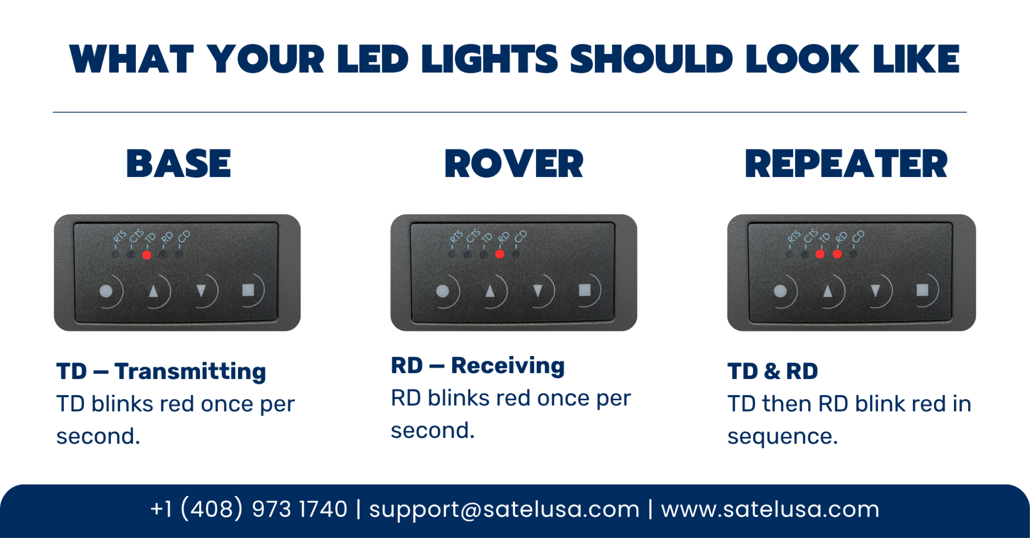
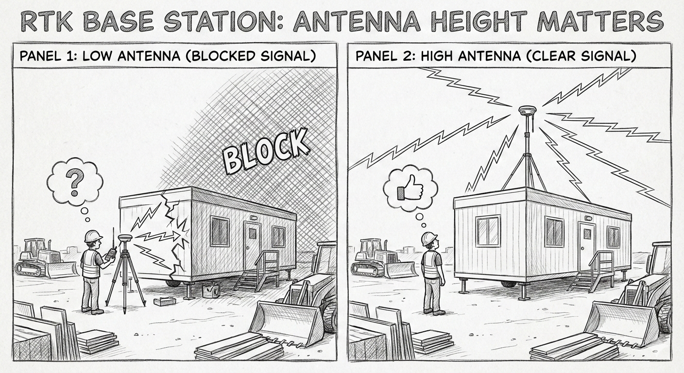
Reliable, long-range communication and stable RTK signals remain essential to keep autonomous equipment performing accurately.
7. Common Data Environments Take Center Stage
Contractors sit on massive amounts of data—most of it underutilized. Common Data Environments (CDEs) solve this.
- One secure hub for design, engineering, fabrication, and field data
- Faster decisions due to unified visibility
- Supports digital twins for long-term asset management
- Reduces miscommunication between field and office
CDEs become a foundation for confident, real-time project control.
8. Smarter Infrastructure Through GIS and AI
Aging infrastructure and expanding demand place heavy pressure on asset owners. GIS-centric Asset Lifecycle Management (ALM) steps up:
- Predictive maintenance reduces lifecycle costs by up to 40%
- GIS + AI highlight risks before they turn into failures
- Agencies shift from reactive repairs to proactive planning
This is especially relevant for utilities, transportation, and public-sector operators who need long-term visibility.
9. Technology Becomes Easier—and More Affordable
A key shift in 2026 is democratization. Technology becomes accessible to contractors who previously lacked the resources.
- Better user experience across tools
- Simplified interfaces reduce training time
- Subscription pricing removes high upfront costs
- E-commerce options allow quick purchasing and deployment
Small and mid-sized contractors will now compete with the speed and precision previously limited to larger firms.
10. Finance and Field Data Finally Sync
Budget overruns often stem from a disconnect between field activity and back-office visibility. In 2026, ERP platforms built for construction close that gap:
- Integrated accounting, HR, timekeeping, and jobcost data
- Live updates from field to office
- Better control during material price swings and tariff changes
- Stronger forecasting due to unified systems
When financial data and field performance align, projects stay predictable.
The Big Picture
Trimble’s 2026 Outlook delivers a clear message: technology is no longer an add-on. It is the operating system of modern construction. AI, automation, training, connected data environments, and more accessible tech will define the next era of project delivery. Contractors who invest early will move faster, reduce downtime, and build with greater confidence. For teams that rely on precise positioning and mission-critical connectivity, these trends all point in the same direction: a future where accurate data, reliable communication, and integrated workflows drive every successful jobsite.