When setting up an RTK radio antenna system, choosing the right cable is important to ensure reliable performance. This guide gives you practical recommendations on cable types and run lengths.
Cable Types
For RTK antenna runs, we focus on two primary options: LMR 240 and LMR 400.
The LMR naming convention is based on the cable’s outside diameter in inches: LMR 400 is approximately 0.400 inches in diameter, LMR 240 is 0.240 inches in diameter.
LMR 400 has lower signal loss and a thicker, stiffer jacket. It’s more durable and best for long cable runs.
LMR 240 is thinner, lighter, and easier to work with. Loss is slightly higher but negligible on shorter runs. For most installs under 50 feet, it’s the more practical choice.
Both cable types also come in an “UltraFlex” variant that uses a stranded conductor instead of a solid one. Its slightly higher loss but easier to work with. UltraFlex cables are good choices for mobile/temporary setups where cables may be frequently handled. Solid core (standard LMR) cables are better for permanent installations and longer cable runs.
LMR 240
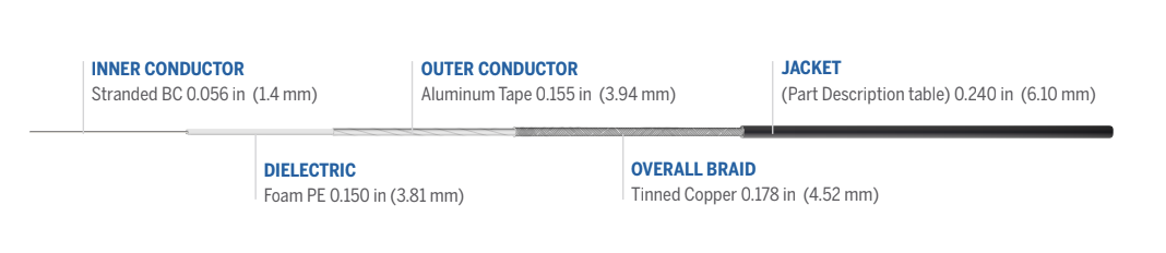
LMR 400
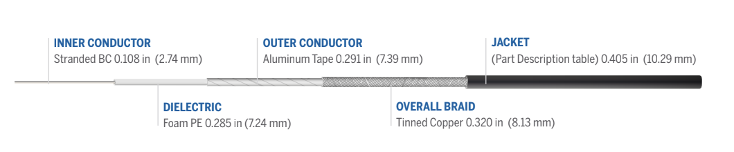
(UltraFlex variations have the same measurements but use stranded conductors)
Cable Length Recommendations
We recommend keeping cable losses under 6dB as a rule of thumb, with under 3dB being even better. These aren’t hard limits – a system with higher loss may also work well, especially if it is shorter range.
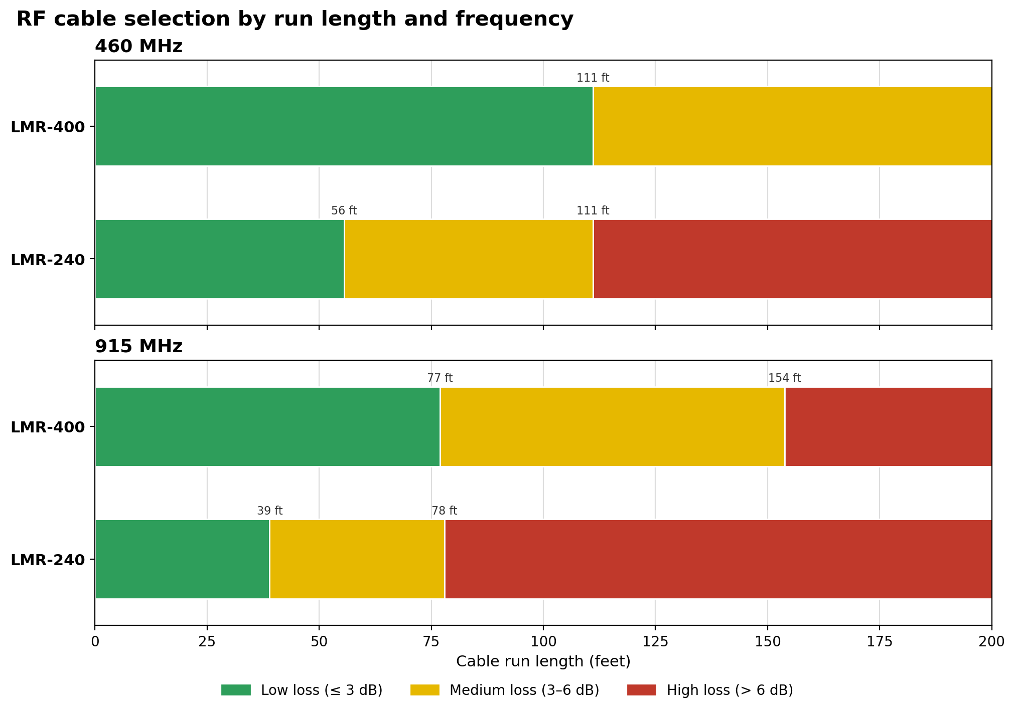
This means:
- Under 50 ft: LMR 240 is the practical choice. Use UltraFlex for frequently handled cables.
- 50 to 100 ft: Either works, but prefer LMR400 for 900MHz or long range links.
- 100 to 150 ft: Use LMR400 to minimize cable loss. You may also consider a higher gain antenna for systems with long cable runs.
- 150+ feet: You may want a thicker cable (LMR600 or better), especially for 900MHz. At some point, a radio repeater may be more practical than a very long cable run.
For installs with tight bends, reach out before you buy. Multi-section runs are sometimes necessary.
Signal Loss Reference
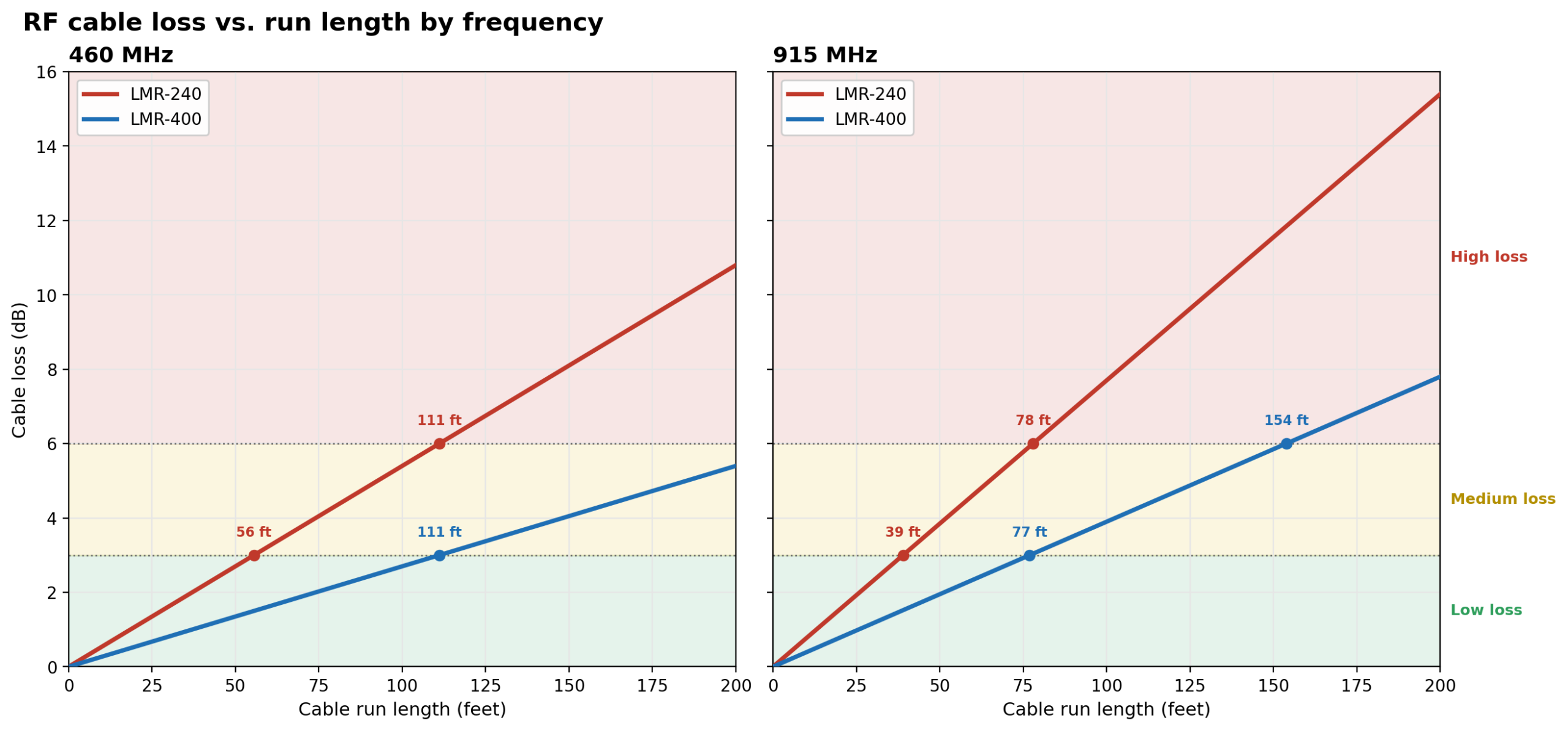
| Loss at 460 MHz / 100 ft | Loss at 915 Mhz / 100 ft | |
| LMR240 UltraFlex | 6.4 dB | 9.2 dB |
| LMR240 | 5.4 dB | 7.7 dB |
| LMR400 UltraFlex | 3.3 dB | 4.7 dB |
| LMR 400 | 2,8 dB | 4.0 dB |
Have a unique install scenario? Contact Satel USA today.
Coming soon: Lightning Arrestors & Weatherproofing | Antenna Cable Installation Tips