Posted on

Tech Note: Why Is My Range Shorter Than Expected?

The Problem

You’re getting great range one day—5 or 6 miles—and the next day you’re only getting a mile. What changed? This is one of the most common questions we hear and the answer may not be what you expect.


The Short Answer

For practical RTK distances, signal loss is about obstructions between your transmitter and receiver—not distance itself.

Your Satel 35W radio has enough power to get to the moon or even farther. But it can’t go through a mile of solid terrain, even though the moon is significantly farther away. That’s the fundamental principle of radio range for typical Satel radio use cases: obstructions matter, distance alone does not.


Why Range Varies Between Locations

Not all locations are created equal. Just because you got 5 miles with your exact same setup at one job site doesn’t mean you’ll get 5 miles at another. Here’s why:

  • Terrain changes – Hills, valleys, and elevation differences
  • Built environment – Earth, metal, and concrete are very effective at absorbing radio waves. Wood and glass will also reduce signals to a lesser degree
  • Natural environment – Trees and other vegetation reduce signal levels
  • Your position on the job site – Working locations on a job site can be drastically different throughout the day

The key insight: You can receive a signal at -70 dBm at 5 miles in one location, and receive the same -70 dBm signal at only 1 mile in another location. The signal strength is the same despite one link being much farther because the obstructions are different.


Basic Troubleshooting Checklist

Before assuming you have a hardware problem, check these basics:

1. Antenna Connections

  • Are all antennas screwed in tight?
  • Are connectors clean, dry, and free of corrosion?
  • Check both base and rover antennas

2. Cable Inspection

  • Look for cracked jackets on antenna cables
  • Check for exposed wiring or visible damage
  • Damaged cables are uncommon but simple to spot

3. Antenna Orientation

  • Antennas need to be oriented the same direction (vertical is most common)
  • Not crooked, tilted, or sideways

4. Antenna Height

  • Is your transmitting antenna as high as possible?
  • There’s potentially a huge difference in range transmitting at 5 feet above ground level vs 10 feet or more
  • Antenna tripods are available for temporary installs that need more height

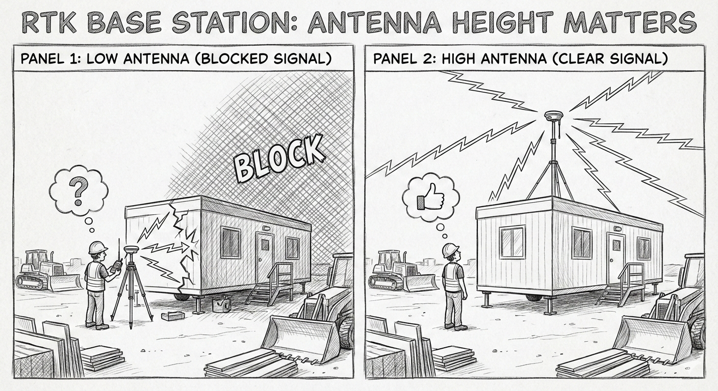
The #1 Solution: Antenna Height

Getting your transmitting antenna higher is the best way to increase range.

Why Height Matters

Higher antennas can “see over” obstructions that would completely block antennas at a lower height. Even a 10-foot increase can sometimes make the difference between no signal and full RTK lock.

Practical Height Solutions

  • Use a tripod with an extension pole – Our K-YKIT-AK (Radio Antenna Tripod) gets you up to 13 feet (4 m) total elevation
    • Tripod extends to 5.5 ft (1.7 m)
    • Telescoping mast reaches 7.5 ft (2.3 m)
    • Combined height: 13 feet (4 m)
  • Mount on top of structures – Construction offices, vehicles, existing buildings
  • Avoid ground-level setups – Shoulder height (~5 feet) is often insufficient for long distances

Example Scenario:

Problem: Base antenna at shoulder height (5 feet) next to the construction office, trying to reach equipment on the other side of the building.

Diagram showing radio signal blocked by building obstruction

Solution: Mount the radio antenna on top of the construction office. This:

  • Eliminates the building obstruction
  • Adds significant height
  • Extends range in the previously blocked direction

Counter-Example: Building a road through a forest with tall trees. Moving your antenna from 5 feet to 10 feet makes no practical difference because the trees are still blocking the signal. In this case, you might need to use a repeater radio or another approach.


What About the Receiver Antenna?

While the transmitting (base) antenna is usually easier to raise, raising the receiving (rover) antenna helps an equal amount. If you can get your rover antenna higher—even by a few feet—it can improve your link strength.


Related Resources


Need help? 

Contact SATEL USA technical support for site-specific guidance and troubleshooting assistance.

Phone: (408) 973-1740
Email: support@satelusa.com

Posted on

Tech Note: SATEL Radio Setup Checks for RTK Base and Rover Links

Purpose

Use this note to troubleshoot common setup issues when a SATEL base radio and rover radio do not pass GNSS correction data.


1) Why do my base and rover radios not communicate (even on the same frequency)?

Most common cause

Mismatched radio settings block the link even when both radios show the same frequency.

Quick checklist (match base and rover)

  • Frequency (MHz)
  • Channel spacing (kHz)
  • FEC / Error Correction (ON or OFF)
  • Radio Protocol / Compatibility (must match)
  • Serial port settings (not needed for repeaters)
    • Baud rate (serial speed)
    • Parity
    • Data bits and stop bits (if used in your setup)

Recommended troubleshooting steps

  1. Confirm both radios use the exact same frequency and channel spacing.
  2. Confirm both radios use the same protocol.
  3. Confirm both radios set FEC the same way (both ON or both OFF).
  4. If the radio connects to a GNSS receiver via serial:
    • Match the radio serial settings to the GNSS receiver serial settings.
    • Verify the GNSS receiver outputs corrections on the same port wired to the radio.

2) What Baud Rate, Parity, and Protocol Should I Use Between SATEL and GNSS?

Rule

The baud rate must match on both ends. If the receiver talks at 38400, the radio port must also use 38400.

Common baud rate examples (receiver dependent)

  • Trimble: 38400
  • Topcon: 38400
  • Carlson: 9600 or 115200
  • Leica: 19200 or 115200

Notes

  • Parity and framing vary by receiver and port profile.
  • Use the GNSS receiver port settings as the source of truth, then mirror them in the SATEL radio.

3) How Do I Confirm My SATEL Radio Is Receiving Correction Data From the GNSS Base?

Primary field check

  • The RD (Receive Data) indicator blinks when the radio receives serial data into the radio.

What it tells you

  • If RD blinks, the base GNSS receiver is likely sending correction data into the radio.
  • If RD does not blink, check:
    • Cable and pinout
    • Port selection on the GNSS receiver
    • Serial settings match (baud, parity, etc.)
    • GNSS base is actually outputting corrections (RTCM, CMR, CMR+)

4) How Do I Configure SATEL Radios for RTCM vs CMR or CMR+?

Key point

SATEL radios transmit data transparently. The radio does not interpret, convert, or modify RTK correction formats.

What you actually configure

  • Set the GNSS base to output the correction format you need (RTCM, CMR, or CMR+).
  • Make sure the rover GNSS is configured to accept that same format.
  • Keep the radio link settings aligned (frequency, spacing, protocol, FEC).

Practical takeaway

If the rover cannot use RTCM (or cannot use CMR/CMR+), fix it in the GNSS configuration, not in the SATEL radio.


Fast Diagnostic Flow (On-Site)

  1. Match radio link settings: frequency, channel spacing, protocol, FEC.
  2. Confirm RD blinks on the base radio.
  3. Confirm rover GNSS accepts the base correction format.
  4. Verify serial port settings match between GNSS and radio.


If you’re still having problems, feel free to contact our support team.

Posted on

Tech Note: High Power Radios and Heat

High power radios like the Satel EASy Pro and EASY Pro+ generate a lot of heat while transmitting, so they can get hot to the touch – especially when it is also hot outside. While output power on these radios is up to 35W, they need as much as 120W of power to generate this signal, with the difference ending up as heat (up to 85W of heat).

If radios are getting too hot, there are numerous ways to reduce or mitigate the amount of heat generated. Many of these techniques will also save power and increase run time on battery systems.

  • Avoid using slow GMSK radio protocols including TrimTalk450 and PacCrest-GMSK if possible. These modes can generate up to twice as much heat as more efficient 4FSK modes, like Satel 3AS or PacCrest-4FSK.
  • Reduce transmit power. Often 25W or even 10W of transmit power is plenty to get the range you require. Additional height on the transmitting antenna system, such as using a tripod or antenna mast system is often more useful than high transmitter power to increase range.
  • Use Satel 3AS mode with no error correction (also known as forward error correction or FEC). Error correction adds significant overhead (approximately 30%) which runs the transmitter longer and is only useful in conditions with extremely poor signals. While disabling error correction can reduce range, this is usually not meaningful for 35W transmitters.
  • Make sure the TD light is not solid green. This indicates the radio is in test mode and this will cause excess heat generated and may disrupt the normal operation of the radio system. A blinking green TD light is expected in normal operation and indicates periodic data transmission.
  • Ensure the radio is mounted vertically (antenna connector facing up), so that air can flow up through the heat sink.
  • Get a 25kHz license. 25 kHz channels are up to twice as fast as 12.5kHz channels, so operating at 25kHz will run the transmitter for shorter periods of time and generate less heat. Note: Operating at 25kHz in the United States requires a license specifically authorizing this use and requires the use of 4FSK or faster compatibility modes.
  • If using an EASy Pro radio, consider upgrading to a EASy Pro+. The EASy Pro+ has a wider range over power outputs (1-35W vs EASy Pro’s 10-35W), and is 20-50% more power efficient, which leads to less heat generated.

Still have questions? Contact us for additional support.

Posted on

Tech Note: Adding a Channel List to the SATELLINE-4Pro

Because the SATELLINE-4Pro is only available with “Survey Mode” firmware, Configuration Manager software is essential for loading a channel list and changing most settings. The most recent version of the software can be downloaded from our Support page.

Following are step-by-step instructions on loading a channel list to your 4Pro radio:

  • Connect the 4Pro to power (check that you have the right voltage).
  • Open SATEL Configuration Manager & click the “Program Preferences” tab.
  • Confirm that the correct COM-port is selected and that the baud rate matches that of the radio (default baud rate of the 4Pro is 115200 bps). (Important: to be able to change settings, in the “Program Preferences” tab, under User Level Settings enter the maintenance password and login.)
  • Select the blue “Connect” tab to fully access the modem settings.
  • Select “Modem Settings” tab
  • Select “Channel Selector”, blue button at the top right.
  • If creating a new channel list, in the Channel Selector Window, select “Add” and the Channel Editor Form will appear. Here you can set the User Channel (1-XX), Tx and Rx Frequencies, Bandwidth (12.5, 20 or 25 kHz), and Channel Tx Power (NOTE: if Tx Power is left blank, the radio will default to the max. power of that unit and the saved channel list can be reloaded to any SATEL radio. See previous blog post here for more information.). Input your selection for the user channel and press OK. Continue this process for each subsequent channel, to complete your channel list. (If loading an existing channel list, in the Channel Selector Window, select “Load”, where you will then be able to browse for your saved CFG or CSF file)
  • It is recommended that you then click the “Save” button, to save your new channel list to your PC.
  •  When done, click “Close”. Change “Channel List In Use” to “ON”. The edited settings will show in red font. 
  •  Select the blue “Write Settings” button. Once complete, these settings will change to black font, indicating they’re loaded to the radio.
  •  We recommend you select “Save Configuration to File” to save all specified settings to your PC, before selecting “Disconnect”.

For additional questions, or if you’d like to suggest a technical topic for us to review in our blog, please email support@satelusa.com.

Posted on

Troubleshooting SATEL Radios

The most frequent cause of Satel Radio issues is a mismatch in settings between the transmitting radio and the receiving radio. The key settings that must be the same on both radios are:

  • Frequency
  • Channel Spacing
  • Radio Compatibility/Protocol
  • Error Correction (FEC)

Note: On other Satel-compatible radios, or via 3rd party interfaces (such as Leica or Carlson Software), these terms may have different names. Other settings, such as Error Checking are uncommonly used.

Troubleshooting Steps

Base Radio

  1. Start with the base/transmitting radio. The “TD” light should be blinking. If it isn’t, that means the transmitting radio is not receiving data via its serial port. Check the settings on the attached device to ensure it is correctly sending data via the serial link.
  2. Note down the 4 above settings using the radio screen and buttons. The settings are found in the following menus:
    1. Frequency: “Radio frequency” menu (“TX & RX freq”)
    2. Channel Spacing: “Radio frequency” menu (“Ch Spacing”)
    3. Radio Compatibility: “Radio settings” menu (“Compatibility”)
    4. Error Correction/FEC: “Additional” menu (“Error corr.”)

Remote Radios

  1. Start by checking received signal strength. In the upper right corner, the number shown with a negative sign is the RSSI. A normal RSSI should be between -40 and -100 or so, with a higher number closer to the transmitting radio, and a lower number farther away. During normal operation the RSSI will likely change between a higher number, such as -60 and a low number (typically -120 or below).
    1. If the number stays low (below -100), the radio is not receiving a signal over the air, which indicates the frequency on the base radio and remote radio is not matching, or the base radio is not transmitting. Check and program the frequency on both radios.
  2. If the signal strength is high (above -100), or changing between a high and low signal, the next step is to check the RD light, which should be blinking. If it isn’t, this indicates a settings mismatch (the radio hears a signal, but can’t decode it). Check and program the 3 other settings (Channel Spacing, Radio Compatibility, Error Correction/FEC).
  3. If the RD light is blinking, but your data still isn’t making it through, check the Baud Rate on the receiving radio (in the “Port 1” menu), and ensure it matches the settings on the device attached to the receiving radio.

Further Troubleshooting

The above steps cover the most common issues seen when setting up a Satel radio system. If the instructions don’t address your situation, or you are unsure how to match settings on a Satel-compatible device, such as a radio from another manufacturer, or via 3rd party configuration software, please contact us.

Posted on

Tech Note: Using Configuration Manager

SATEL Configuration Manager is an essential tool for loading settings to your SATEL modems. One feature that can make that fast and easy is the ability to load settings from a pre-existing file. That way, if you need to load the same settings and/or a channel list on multiple units, you don’t need to individually key in the settings for each one. The settings of the first unit you set up can be saved to your PC by clicking on “Save Configuration to File”. On the next radio you set up, click “Load Configuration from File” and “Open” the cfg file that was saved. When completed, all loaded settings are red and an info tablet opens stating “Configuration file loaded successfully!”. The settings are then uploaded to the radio by clicking “Write Settings” on the top tab of Configuration Manager. Settings files should only be used across matching models, so settings for the EASy 1W should not be loaded to the EASy Pro 35W, for example.

When in Survey Mode, there is a helpful feature specifically for channel lists. You can save the channel list separately and in a format that can be used across SATEL radio models, as long as the “Tx Power” setting is set to “0”, indicating that the maximum power can be used. Select the “Program Preferences” tab, enter password for maintenance mode, then in “Modem Settings” select “Open Channel Selector”. Build your channel list by selecting “Add” and remember to put “0” in “Tx Power” (unless you have restrictions that prohibit you from doing so). Select “Save” to save the channel list to your computer to load to other radios. Select “Load” to load to your current radio, then click “Write Settings”.

Note that the Satelline-4Pro requires Configuration Manager version 1.6.1—that and the Configuration Manager User Guide can be found on our website, under Service>Software.

Posted on

Tech Note: What is Error Correction?

Error Correction is an available setting in all SATEL radio modems, which can help improve data transfer in cases of poor or unreliable communication. Referred to as FEC Mode (Forward Error Correction) in Configuration Manager, note that this setting refers to SATEL 3AS Error Correction and does not affect other compatibility modes, such as PacCrest. This setting can be turned ON or OFF both in Configuration Manager and directly on the front screen of your radio modem.

When Error Correction is enabled (ON), the radio modem automatically adds additional error correction information, which increases the amount of transmitted data by 30%. It is used by the receiving radio modem to correct erroneous bits, as long as the ratio of correct and erroneous bits is reasonable. The resulting benefit can be an improvement of up to 3dB sensitivity.

Error Correction improves the reliability of data transfer via the radio interface, especially in unfavorable conditions. The Error Correction function should be used when link distances are long or received signal is otherwise low due to poor propagation conditions or multi-path fading. It is also recommended to use Error Correction in case there are intermittent interferences on the radio channel.

The Error Correction function decreases data transfer throughput by approximately 30%. Though transfer delays are longer, Error Correction can be quite useful for the best data transmission quality in the scenarios described above.

Posted on

Tech Note: Speed vs Modulation

Few radio parameters can be as confusing as modulation and over-the-air speed, not only for the novice user, but also for the experienced. Here are a few comments that hopefully help to shine some light on the subject:

Over-the-Air Speed

Although Port Speed and over-the-air speed have some relation to each other, they are totally separate settings.

While the Radio Port speed and GPS receiver Port speed must match exactly (for example GPS = 9600 bps & Radio = 9600bps), to allow the normal transfer of data over the connecting cable, the speed over-the-air cannot be set by simply changing the Port speed. It’s actually a fixed value which depends on both bandwidth and modulation.

In the US, the most common bandwidth today is 12.5kHz. So if your radio uses any of the following modulations:

– SATEL 4FSK, PacCrest 4FSK, PacCrest FST at 12.5kHz,

the speed over the air is fixed at 9600bps.

Whereas if you are using the following modulations:

– PacCrest GMSK, or Trimtalk 450S at 12.5 kHz, the speed over the air is fixed at 4800bps.

If a half-speed modulation type such as GMSK is used, the Base radio Transmitter is on-the-air for twice the length of time respect to a faster modulation. This means higher battery consumption and more overheating of the radio itself.

Modulation

Modulation can be an even more complex subject and it has a major influence on both the speed over the air and the actual range of the radio equipment.

The most common modulation today is 4FSK (4 Frequency Shift Keys). This means that the radio transmitter (base) transforms the NMEA data from the GPS into radio frequency variations that shift to 4 different points around its central working frequency. All the points must be contained within the 12.5kHz required by the FCC. This means that the TX will constantly “shift” to 4 frequency points, up to 6.25 kHz away from its central frequency, both to the right and to the left in the frequency spectrum.  A rough example: the Tx “shifts” from its central 450.000000 MHz to -> 450.006250 MHz and then back and forth from and to -> 449.9993750 MHz.  Each “shift” is interpreted as a data 1 or zero and the whole NMEA string of the GPS is recomposed in the rover.

Some equipment offer even higher over-the-air speed by using more complex types of modulation (ex. 8FSK, 16FSK). Some even use 32QAM, where not only frequency “shifts” but also “phase” variations are measured. SATEL offers an internal OEM module, already in production and used by major GPS manufacturers, with 8FSK and 16FSK modulation and over-the-air speed up to 14400bps.  This becomes useful when several constellations are received (for example GPS + GLONASS), which cause the radio to transmit more data. In order to be able to contain all data within 1 Hz (once a second) a higher over-the-air speed is desirable. The downside of higher modulation is that the receiver must work harder to detect very small variations, thus a stronger radio signal is required to counterbalance the environmental noise present in the air. Ultimately this means a decreased working range.

Posted on

Tech Note: Using a Repeater

Repeater Mode can be easily set up from the front screen of any SATEL radio (Main Setup>Additional>Repeater>select ON>Save changes). Many SATEL users stop there, however additional steps can be taken in order to prevent potential issues with your system. Some rather common issues we hear about when a repeater is in place are:

“I get a signal when near the base, but not when near the rover”

“I’m getting a signal, but not getting a fix”

“The rover sometimes hears both the base and repeater and it looks to be creating issues with my GPS”

The first scenario is likely an antenna issue; you will want to check your antennas and cables. The second scenario is likely due to parameters; you will want to go back through your settings and make sure parameters match. The last issue of an “echo” or double signal is a common problem you’ll experience with a repeater, especially in Precision Ag applications, or other scenarios in which the rover is moving. Some GPS are immune to the echo, while we’ve seen others get confused by the double signal. Here are some tips for fixing this common issue, depending on your licensing:

If You Have More Than 1 Frequency:

If in your licensing you have more than one frequency available for use, we recommend using separate TX/RX frequencies. For example, let’s say you have 469 MHz and 462 MHz available. You would set up the base to transmit at 469 MHz. You would set up the repeater to receive at 469 MHz (Main Menu>Radio Frequency>RX Frequency (change setting)) and to transmit at 462 MHz (Main Menu>Radio Frequency>TX Frequency (change setting)). Then you will set the rover to receive at 462 Mhz. This will ensure that even if the rover hears the base at times, it will not receive and interfere with the communication.

If You Do Not Have More Than 1 Frequency:

The alternative option, if you do not have more than one frequency available to use in your application, is to set up addressing. This is easily done through the programming software on your PC, using either Configuration Manager or SaTerm. The set up would look like this:

Base = Address 0001 0001

Repeater = Receive Address 0001 0001, Transmit Address 0002 0002

Rover = Address 0002 0002

As above, this also ensures that the base will not interfere with the rover, even if a double signal can be heard at different points.

Other Common Issues:

Another common issue in repeater set ups relates to modulation settings. Using a slower protocol, such as GMSK, is not recommended on a repeater set up because of the length of the data stream. The data string nowadays are so long that it can create a back up of data; the repeater may still be transmitting to the rover as the base is trying to send the next string. This can be resolved by using a faster protocol.

Set up should also be considered; we have seen numerous situations in which the repeater is placed too close to the base, instead of near the rover. You want to make sure the repeater and rover are as close as possible in order to ensure the best signal.

Double repeater set ups are much more complicated, especially when the rover is moving. Addressing, as described above, is recommended in this scenario.